
Hull Corrosion Protection in Floaters: Impressed Current vs. Sacrificial Anodes
Cathodic protection (CP) is a cornerstone of asset integrity for floating offshore units—FPSOs, FLNGs, FSUs—as well as for ships and fixed structures like jackets. In the chloride-rich marine environment, unprotected steel will corrode, jeopardizing structural integrity, safety, and lifecycle economics. Two CP approaches dominate practice: Impressed Current Cathodic Protection (ICCP) and Sacrificial Anode Cathodic Protection (SACP). While both aim to shift steel surfaces to a protective potential where anodic dissolution is suppressed, they diverge materially in design philosophy, hydrodynamic behavior, operations, and maintenance.
Floaters live in a demanding environment: continuous immersion in seawater, cyclic loading, coating holidays from mechanical damage, biofouling, variable temperatures, and often limited access for inspection. FPSOs and FLNGs cannot normally return to dry dock, so the cathodic protection system must be capable of protecting the hull effectively for normally 20+ years without relying on dry-docking. Even modest corrosion rates—if left unchecked—can translate into significant thickness loss across large hull areas over multi-decade lifetimes. Effective CP complements high-quality coating systems, targeting coating defects and crevices where localized corrosion initiates. The right CP choice can reduce offshore maintenance campaigns and stabilize OPEX.
The Fundamentals: ICCP vs. SACP
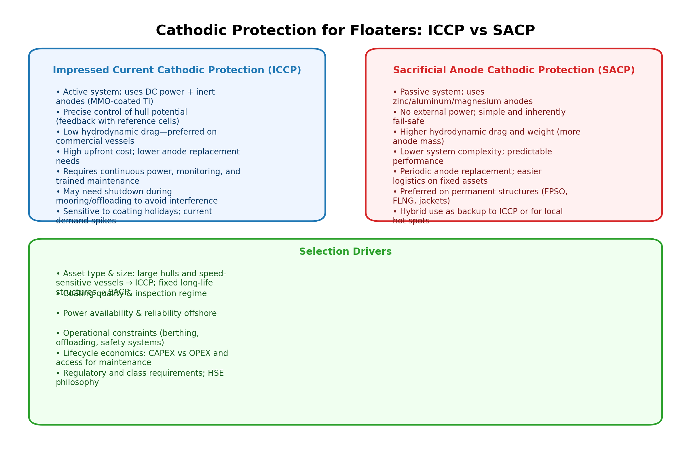
Sacrificial Anode CP (SACP) uses consumable anodes—commonly zinc or aluminum alloys offshore—that possess a more negative electrochemical potential than steel. By electrically bonding these anodes to the hull, they preferentially corrode, “sacrificing” themselves to polarize the steel cathodically. SACP is passive, power-free, and inherently fail-safe.
Impressed Current CP (ICCP) employs inert anodes (e.g., titanium with mixed-metal-oxide coating) powered by a DC rectifier. Reference electrodes feed back the hull potential to a controller, which adjusts current to keep the steel within a protective range. ICCP’s hallmark is precise control and the ability to deliver higher current densities efficiently to very large structures with fewer anodes compared to SACP.
Mooring Line Polarization on Stationary Floaters:
FPSOs and FLNGs typically use extensive mooring systems (chains or wires) that are electrically continuous with the hull. Both ICCP and SACP will polarize these mooring lines, but the implications differ. For ICCP, mooring lines can draw significant current, increasing rectifier load and risking overprotection, which may lead to hydrogen embrittlement or coating damage. Mitigation strategies include electrical isolation of mooring lines, dedicated CP design for mooring components, and monitoring potentials during ICCP operation. For SACP, the risk of overprotection is lower, but anode sizing must account for the additional surface area to avoid premature depletion. This issue is unique to stationary floaters and does not apply to commercial vessels, which do not have permanent mooring systems.
Mitigation Strategies:
Electrical isolation of mooring lines using insulating sleeves or connectors.
Dedicated CP design for mooring components (e.g., separate galvanic anodes).
Monitoring potentials on mooring lines during ICCP operation.
ICCP control logic adjustments or temporary shutdown during mooring/offloading.
Hydrodynamics & Vessel Type: Speed vs. Stability
Commercial vessels—tankers, bulk carriers, container ships, cruise ships—are highly sensitive to drag and fuel efficiency. ICCP systems use small-profile inert anodes and flush hull-mounted reference cells, adding negligible form drag. In contrast, SACP requires more anode mass and frontal area, which increases resistance in the boundary layer. Over a vessel’s trading life, even small drag increments compound into meaningful fuel penalties and speed reductions. Hence, ICCP is the default on most modern merchant vessels where speed, fuel economy, and long-range operations prevail.
For permanent structures—such as FPSOs or FLNG on station for 15–25 years, or fixed jackets—the selection calculus changes. While ICCP can protect large hulls effectively, SACP is often preferred because it is simpler, has fewer failure modes, and offers operational resilience regardless of power availability. Although anodes consume over time and may require periodic replacement, planned renewal during in-water campaigns or dry-docking is predictable and integrates well with subsea maintenance windows.
Operational Constraints: When ICCP Must Be Turned Off
ICCP’s active nature introduces operational considerations. During mooring, berthing, or offloading—especially when electrical bonding to other vessels or terminals occurs—there can be concerns about stray current pathways and interference with instrumentation or safety systems. Safety protocols may require temporarily disabling ICCP to avoid unanticipated current flow through connected equipment. This motivates redundancy or hybrid strategies and emphasizes that operational procedures and CP design should be developed in tandem.
Coatings, Current Demand, and Monitoring
Both ICCP and SACP rely on coatings to limit current demand. Coating holidays (or defects/damages) can spike current requirements. ICCP’s closed-loop control reacts quickly to maintain protective potentials but may indicate persistent high current draw if coating damage is widespread, signaling inspection/repair needs. SACP’s current output scales with anode potential and seawater chemistry; it passively follows demand, which is why anode distribution planning is essential. Reference potential surveys and periodic current logging are vital to confirm protection and identify under-protected zones.
Lifecycle Economics
ICCP:
Higher CAPEX for rectifiers, controls, cabling, and inert anodes, but lower anode mass and longer intervals between physical replacements.
OPEX involves monitoring and specialist maintenance.
SACP:
Potentially lower CAPEX in electronics (none) but higher anode material cost, especially on large hulls and jackets.
OPEX is dominated by planned anode renewal and inspection campaigns. On permanent structures, this is predictable and often easier to integrate with routine subsea maintenance windows, with fewer operational failure modes overall.
Hybrid Cathodic Protection Systems (ICCP + SACP)
Hybrid CP intentionally combines impressed current and galvanic anodes to leverage complementary strengths and provide resilience during operational constraints. Typical configurations include:
ICCP as the primary system for broad, controllable protection; SACP is installed in local hot spots (e.g., splash/tide zones, bilges, appendages, caissons) to ensure minimum baseline polarization when ICCP is offline.
SACP as the primary system on fixed jackets or long-life floaters; small ICCP arrays are added near complex geometries or shielded areas (under decks, near risers) where galvanic current distribution is challenged.
Fail-operational design: ICCP provides optimized current during normal operation; if ICCP must be shut down for mooring/offloading or loses power, the SACP layout maintains protective potentials until ICCP is restored.
Smart monitoring: reference electrodes, current transducers, and data logging to track hull potentials and current demand. Trends trigger inspection or coating repair and help tune ICCP output to reduce overprotection risks.
Design notes for hybrid CP: ensure electrical continuity across hull sections and appurtenances; mitigate shadowing through anode placement; consider coating breakdown factors; define ICCP shutdown/startup procedures; and verify potentials by survey after any operational change.
International Standards and Software for CP Design
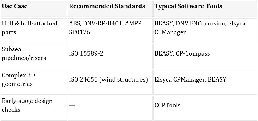
The following international standards provide guidelines for cathodic protection design on FPSOs, FLNGs, and other offshore structures:
ABS Guidance Notes on Cathodic Protection of Offshore Structures (2018): Guidance for CP on FPSOs and stationary offshore units.
DNV-RP-B401: Cathodic Protection Design (2021): Recommended practice for galvanic anode design and ICCP systems for offshore structures.
ISO 15589-2:2024: Cathodic protection of pipeline transportation systems — Part 2: Offshore pipelines; often referenced for risers and subsea components.
ISO 24656:2022: Cathodic protection of offshore wind structures; applicable methodologies for large steel structures.
AMPP/NACE SP0176-2022: Corrosion control of submerged areas of permanently installed steel offshore structures associated with petroleum production.
Common software tools used for CP design and analysis include:
BEASY Corrosion & CP: 3D simulation software for ICCP and SACP modeling on ships and offshore structures.
DNV FNCorrosion: Integrated corrosion analysis within SACS for offshore structural CP design.
Elsyca CPManager: CAD-integrated tool for ICCP/SACP design, compliant with DNV and NACE standards.
CP-Compass®: Cloud-based CP design and verification tool supporting ISO and DNV standards.
CCPTools: Mobile/web app for quick CP design estimates and preliminary calculations.
ICCP vs. SACP (Key Differences)
Summary
Hull corrosion protection is a critical aspect of asset integrity for floating offshore units such as FPSOs and FLNGs, which remain on station for 20+ years without dry-docking. Two primary cathodic protection (CP) methods dominate offshore practice:
Impressed Current Cathodic Protection (ICCP): Active system using inert anodes and DC power for precise control. Preferred for commercial vessels due to minimal drag and fuel efficiency.
Sacrificial Anode Cathodic Protection (SACP): Passive system using zinc or aluminium anodes. Favoured for stationary floaters and jackets for simplicity, reliability, and independence from power supply.
Key Considerations:
ICCP may require shutdown during mooring/offloading to prevent stray current interference.
Mooring line polarization is a critical issue for stationary floaters; ICCP demands isolation and monitoring, while SACP requires proper anode sizing.
Hybrid CP systems (ICCP + SACP) offer resilience and redundancy.
International standards such as DNV-RP-B401, ISO 15589-2, ISO 24656, ABS Guidance Notes, and NACE SP0176 guide design.
Advanced software tools like BEASY, Elsyca CPManager, and DNV FNCorrosion support accurate modeling and lifecycle optimization.
Selecting the right CP strategy depends on asset type, operational constraints, and lifecycle economics. For FPSOs and FLNGs, SACP or hybrid systems are often the most practical choice to ensure long-term hull protection without dry-docking.
References (APA Style)
· Det Norske Veritas (DNV). (2021). DNV-RP-B401: Cathodic protection design. DNV AS.
· International Organization for Standardization. (2024). ISO 15589-2: Oil and gas industries including lower carbon energy — Cathodic protection of pipeline transportation systems — Part 2: Offshore pipelines (3rd ed.). ISO.
· International Organization for Standardization. (2022). ISO 24656: Cathodic protection of offshore wind structures. ISO.
· American Bureau of Shipping (ABS). (2018). Guidance Notes on Cathodic Protection of Offshore Structures. ABS.
· Association for Materials Protection and Performance (AMPP). (2022). NACE SP0176-2022: Corrosion control of submerged areas of permanently installed steel offshore structures associated with petroleum production. AMPP.
· Immonen, E., Eriksson, K., & Haavisto, J. (2021). Computational hydrodynamic optimization of galvanic anode shapes for tunnel thrusters. Journal of the Brazilian Society of Naval Engineering. https://doi.org/10.1007/s40868-021-00096-6
· Zakki, A. F., Rindo, G., Ridwan, M., & Windyandari, A. (2021). Hydrodynamic characteristics of fin-shaped geometry for sacrificial anode body to reduce the hull appendages effect. International Review on Modelling and Simulations, 14(6), 399–407. https://doi.org/10.15866/iremos.v14i6.20067
