
Mechanical Power Limits and the Real Ceiling of LNG Train Capacity
One of cinema’s most iconic engineering moments appears in Star Trek (2009), when Captain James T. Kirk urgently shouts for more thrust from the warp engines as the Enterprise faces imminent destruction. It’s a scene built entirely around raw propulsion and mechanical limits: Kirk demands more power, pushing the machinery beyond its operational boundaries, while the chief engineer struggles to deliver against fixed physical constraints. The franchise is famous for such power‑demanding exchanges, with lines like “Give me more power!” becoming synonymous with the desperate search for additional engine output. This association with power‑limit tension places Star Trek among the most recognized film references for heroic engineering under constraint, highlighted alongside other timeless cinematic quotations in major compilations of famous movie lines.
This moment resonates deeply with LNG liquefaction engineering. No matter which process a designer chooses — SMR, C3MR, DMR, or others — there is always a hard limit to how much liquefaction capacity one train can produce, dictated not by the thermodynamics alone but by the mechanical power of the refrigerant compressors.
Just like in the film, wanting “more power” does not make it magically available. The physics of the machinery rule the outcome.
With this framing, we now examine the liquefaction cycles themselves.
Maximum practical driver size for FLNG – LM9000
The Baker Hughes LM9000 is the most powerful aeroderivative turbine currently suitable for offshore liquefaction duty. Its mechanical shaft rating is approximately 65 MW, which becomes the effective upper limit of drive power for a single‑string SMR liquefaction train on an FLNG hull.
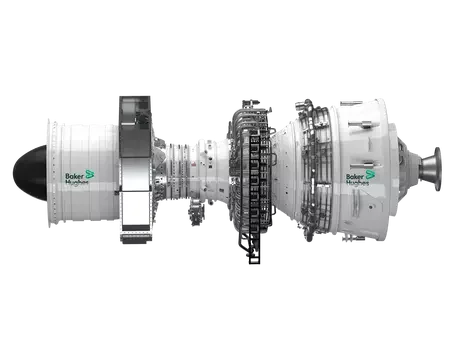
BakerHughes LM9000, source: BakerHughes.com
For a Single Mixed Refrigerant (SMR) liquefaction process (PRICO®, IPSMR®, or similar), this 65 MW limit translates into a maximum practical LNG production capacity of roughly 2 MTPA per train under typical offshore conditions.
https://www.bakerhughes.com/gas-turbines/aeroderivative-technology/lm9000-aeroderivative-gas-turbine
This aligns with real‑world engineering practice:
SMR cycles require most of their power for the single main refrigerant compressor, so train capacity scales almost linearly with available driver power.
With only one compressor string, the turbine size directly sets the ceiling.
To go beyond the ~2 MTPA limit while still using aeroderivative drivers, operators must deploy two parallel compressor strings, each driven by its own turbine — a 2×50%.
Beyond allowing larger liquefaction capacity, parallel compressor strings (2×50%) significantly increase overall train availability, which is a critical consideration for FLNG operations.
In a 1×100% compressor configuration, a single turbine or compressor trip leads to a full train shutdown, stopping liquefaction entirely.
In contrast, a 2×50% configuration allows the train to continue producing LNG at reduced rates even when one compressor string is offline for:
maintenance
inspection
minor failures
turbine trips
This redundancy is particularly valuable for offshore units, where troubleshooting, spare‑part logistics, and mechanical interventions are more constrained than onshore. For FLNG developers, this translates directly into:
Higher annual LNG output
Fewer unscheduled shutdowns
Improved payback and NPV
Greater flexibility during upset and transient operation
In practice, many operators consider parallel compression not just a method for increasing capacity beyond the ~65 MW LM9000 limit, but also as a strategic way to maximize uptime for revenue-critical floating assets.
This philosophy is coming at the cost of:
More footprint
More weight on the hull
More complexity in piping, manifolds, and surge control
Reduced simplicity compared to the 1×100% model
Higher capital cost of the plant
Why DMR and C3MR can exceed these limits (onshore) — but not offshore
Onshore LNG megatrains often exceed 8–10 MTPA, but they do so using:
Frame‑type heavy industrial gas turbines (e.g., Frame 7, Frame 9)
Large electric motors powered by dedicated power plants
These are far too heavy, too large, and too vibration‑sensitive for floating service. Thus:
Offshore → aeroderivative turbines only → mechanical power limit → capacity limit
Onshore → heavy‑frame machines allowed → more power → larger trains
This constraint explains why modern FLNG projects cluster around the 1.4–2.0 MTPA scale per SMR train unless using multi‑train systems.
Conclusion
By incorporating the real-world constraint of mechanical drive power, we gain a more complete understanding of why:
SMR trains on FLNG rarely exceed ~2 MTPA,
IPSMR® and PRICO® dominate mid‑scale deployments,
DMR becomes necessary for >3 MTPA FLNG but at significant capex and mass penalties,
onshore and offshore liquefaction scales diverge structurally, driven not just by thermodynamics, but by the physics of rotating machinery.
APA Reference List
Air Products. (n.d.). Mixed Refrigerant LNG Process (C3MR). Gulf Oil & Gas. https://www.gulfoilandgas.com/webpro1/prod1/services.asp?id=243 [airproducts.com]
Air Products. (2024, May 6). Air Products Announces Successful Performance Test of AP-DMR™ LNG Process Technology for Coral South FLNG Facility. https://www.airproducts.com/company/news-center/2024/05/0506-air-products-successful-test-of-lng-process-technology-for-coral-south-flng-facility
Black & Veatch. (2026). PRICO®: Proven LNG liquefaction for onshore and floating, modular solutions. https://www.bv.com/what-we-do/fuels/prico [files.char...stries.com]
Chart Industries. (n.d.). Standard LNG Liquefaction Plants (C100N Nitrogen Cycle & IPSMR®). https://files.chartindustries.com/Standard-LNG-Liquefaction-Plants.pdf [chartindustries.com]
Chart Industries. (2024, July 22). Chart Industries’ IPSMR® Process Technology Delivers First LNG at New Fortress Energy’s Fast LNG Project. Yahoo Finance. https://finance.yahoo.com/news/chart-industries-ipsmr-process-technology-103000188.html [static.mac...etools.com]
Gastech / Black & Veatch. (2020). PRICO (LNG) Process by Black & Veatch Pritchard Inc. Oil & Gas Process Engineering. https://www.oilngasprocess.com/gas/prico-lng-process-by-black-veatch-pritchard-inc.html [files.char...stries.com]
Linde Engineering. (n.d.). Small- to Mid-Scale LNG (StarLNG® SMR and LICOM® N₂ cycle). https://www.linde-engineering.com/products-and-services/process-plants/natural-gas-processing/small-to-mid-scale-lng-plants [linde-engi...eering.com]
Linde Engineering. (n.d.). Mixed Fluid Cascade (MFC®) Process – Snøhvit LNG Experience. ResearchGate. https://www.researchgate.net/publication/277191472_Mixed_Fluid_Cascade_Experience_and_Outlook [honeywell.com]
Shell Global. (2025). Shell LNG Technology – Dual Mixed Refrigerant (DMR). https://www.shell.com/business-customers/catalysts-technologies/licensed-technologies/lng-technology.html [offshore-energy.biz]
LinkedIn. (2026). APCI C3MR: A Key Process in LNG Liquefaction Technology. https://www.linkedin.com/pulse/apci-c3mr-key-process-lng-liquefaction-technology-bogdan-karaglanov-nakue/ [energycurated.com]
Springer / WCFS. (2024). Case Studies of SMR Liquefaction for FLNG Applications. https://link.springer.com/chapter/10.1007/978-981-97-0495-8_33 [chartindustries.com]
Energy XPRT. (2016). Black & Veatch PRICO SMR Becomes World’s First Proven FLNG Technology to Achieve Production on a Floating Facility. https://www.energy-xprt.com/news/black-veatch-prico-smr-becomes-world-s-first-proven-flng-technology-to-achieve-production-on-a-float-678811 [uop.honeywell.com]