
FLNG 101: Bringing the LNG Plant Offshore
Despite attracting significant industry attention over the last decade, FLNG remains a relatively small segment of the offshore energy market. At August 2026, 15 FLNG facilities are either in operation or under construction worldwide, with 8 units already delivered and 7 additional projects currently being built or converted. As experience accumulates and costs continue to decrease, FLNG is increasingly being considered a viable alternative to onshore LNG developments for the monetization of offshore gas resources.
A Floating Liquefied Natural Gas (FLNG) facility is an offshore floating production unit designed to receive natural gas from subsea reservoirs or a sealine, process it, liquefy it, store it onboard, and transfer the LNG to specialized carriers for export.
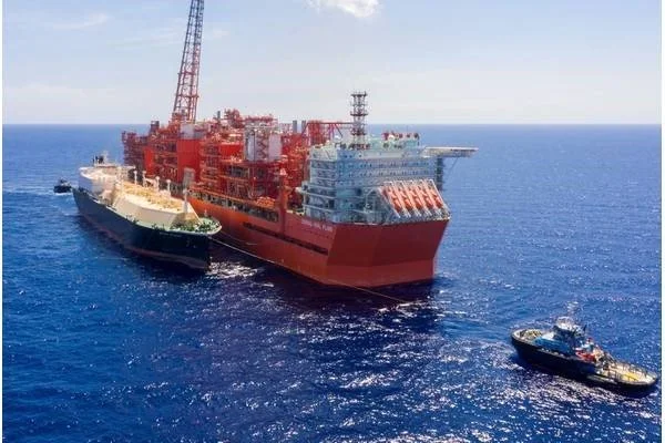
Coral South FLNG. Source: Eni
The term FLNG can be broken into two distinct components:
Floating
The word Floating means that the facility is installed on a marine vessel or hull rather than onshore. Depending on the project requirements, the unit may be:
Permanently moored to the seabed for its entire operating life.
Disconnectable, allowing the vessel to temporarily leave location in the event of extreme environmental conditions such as cyclones or hurricanes.
Being a floating facility brings many of the systems typically found on ships and offshore platforms, including:
Accommodation and living quarters
Essential power generation
Ballast systems
Potable water production and distribution
Wastewater treatment
Fire and gas systems
Navigation and communication systems
Mooring systems
Marine cargo handling facilities
In essence, an FLNG must function both as an industrial processing plant and as a self-sufficient offshore vessel.
We discussed about mooring technologies and living quarters in previous articles of Floaters Intelligentia.
Liquefied Natural Gas
The second part of the acronym refers to the facility's primary product: Liquefied Natural Gas (LNG).
Natural gas extracted from the reservoir cannot normally be liquefied directly. Before entering the liquefaction process, it must undergo several treatment steps to remove contaminants and meet LNG product specifications.
A typical FLNG process includes:
Gas pre-treatment
Hydrocarbon fractionation
Liquefaction
Cryogenic storage
LNG offloading
The result is a transportable liquid product whose volume is approximately 1/600th of the original gas volume, enabling economical transportation across the world.
If the gas is coming from a sealine, thus has a stable flow and know inline conditions, pre-treatment can be simpler.
A Simplified FLNG Process Flow Diagram
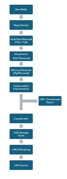
In some FLNG designs, additional fractionation columns may be installed downstream of the gas processing section to recover components required for onboard refrigerant manufacture.
Why Is Each Processing Step Required?
1. Slug Catcher
The first piece of process equipment typically encountered is the slug catcher.
Gas arriving from subsea wells rarely flows as a perfectly stable gas stream. Variations in flow regime can generate large liquid slugs containing condensate and water. The slug catcher acts as a buffer vessel that stabilizes incoming production and protects downstream equipment from process upsets.
Its primary functions are:
Stabilize flow from the wells
Separate bulk liquids from gas
Protect downstream process units from large liquid slugs
Improve overall plant operability
2. Acid Gas Removal Unit (AGRU)
The gas then enters the Acid Gas Removal Unit where carbon dioxide (CO₂) and hydrogen sulfide (H₂S) are removed.
This step is critical because:
CO₂ can freeze at cryogenic temperatures and block heat exchangers and process equipment.
H₂S is highly corrosive and incompatible with the cryogenic section of the plant.
Both components negatively affect LNG product specifications.
Amine-based absorption systems are commonly used for this service. The removed acid gases are typically routed to thermal oxidizers, incinerators, sulfur recovery systems, or other disposal facilities depending on project design and environmental regulations.
3. Dehydration Unit
After AGRU, the natural gas is saturated with water. Even trace amounts of water can become a major problem once gas enters the cryogenic section.
At LNG temperatures, water freezes and can form ice or hydrates capable of plugging process equipment.
The dehydration unit reduces water content to extremely low levels before liquefaction.
Typical objectives are:
Prevent ice formation
Prevent hydrate formation
Protect cryogenic equipment
Maintain LNG product quality
Molecular sieve dehydration systems are commonly used on FLNG facilities. The molecular sieve beds are regenerated onboard with dry gas from the process.
4. Mercury Removal Unit
Mercury is typically present in natural gas reservoirs in very small concentrations. Despite these low concentrations, its removal is essential.
Many cryogenic heat exchangers are manufactured from aluminium alloys because of their excellent thermal conductivity and performance at low temperatures.
Mercury can react with aluminium and lead to liquid metal embrittlement and corrosion-induced cracking, potentially causing catastrophic damage to cryogenic equipment.
For this reason, mercury removal beds are installed upstream of the liquefaction section.
Mercury removal unit is normally an absorption bed that has same lifetime of the plant.
5. Hydrocarbon Fractionation
After contaminants have been removed, the gas can be considered "sweet rich gas" and can enter the hydrocarbon recovery and fractionation section.
The key separation in most LNG plants is performed in the demethanizer column, where methane is recovered overhead as feed to the liquefaction section, while heavier hydrocarbons are recovered in the bottom stream for LPG and condensate production.
Removal of heavy hydrocarbons also prevents freezing and operational issues in the liquefaction section, while ensuring the LNG heating value remains within commercial specifications.
Depending on the reservoir composition and project economics, this section may recover:
Ethane
Propane
Butane
LPG products
Condensate
The methane-rich stream then becomes the feed gas for the liquefaction section and is called also “sweet lean gas”.
In some FLNG developments, part of these recovered hydrocarbons may also be used as feedstock for the refrigerant system.
6. Liquefaction
The liquefaction section represents the heart of the FLNG facility.
Natural gas is progressively cooled until it reaches approximately -162°C, at which point methane becomes a liquid. At that temperature and in liquid form, the natural gas shrink 600 times.
The basic thermodynamic concept is exactly the same as the refrigerator or air-conditioning system found in a home: a refrigerant circulates in a closed loop, absorbing heat from one location and rejecting it elsewhere.
The difference is scale.
A domestic refrigerator removes a few hundred watts of heat. An FLNG liquefaction train continuously removes hundreds of megawatts of heat while processing millions of cubic metres of natural gas every day.
Depending on the liquefaction technology, refrigerants such as nitrogen, methane, ethane and propane may circulate continuously in dedicated refrigeration loops and can represent a significant fraction of the process inventory onboard.
Modern LNG plants typically require approximately 0.25 to 0.30 kWh of energy per kilogram of LNG produced, making liquefaction one of the most energy-intensive industrial operations in the hydrocarbon industry.
One of the key differentiators between an FLNG and an FPSO is therefore the presence of massive refrigeration compressors, cryogenic heat exchangers, condensers and cooling systems needed to reject the heat removed from the natural gas stream.
We already discussed about LNG liquefaction technologies at this article.
7. LNG Storage and Offloading
Once liquefied, LNG is transferred to insulated cryogenic storage tanks integrated into the hull.
The LNG is then periodically offloaded to LNG carriers for transportation to regasification terminals and end users around the world.
LNG storage technologies has already been discussed in this article of Floaters Intelligentia.
8. Main Products of an FLNG
An FLNG does not necessarily export LNG only. Depending on the reservoir composition and process configuration, the facility may produce:
LNG (main product)
Condensate
LPG (propane and butane)
Refrigerant make-up streams
Fuel gas for onboard power generation
Conclusion
An FLNG combines two worlds in a single facility. The floating element brings all the complexity of a permanently moored offshore vessel, while the LNG element adds a sophisticated gas treatment, fractionation and cryogenic liquefaction plant.
Understanding the sequence from slug catcher through pre-treatment, fractionation, liquefaction, storage and offloading provides the foundation for understanding every major process system onboard an FLNG. At its core, an FLNG is essentially the world's largest floating refrigeration plant, transforming natural gas from an offshore reservoir into a globally traded energy product.
